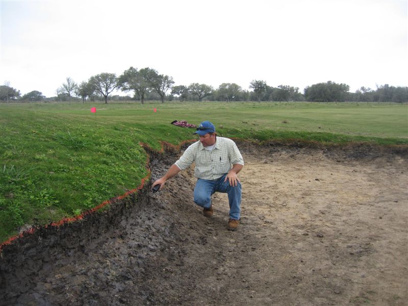
 Don has started our final major task - detail bunker work. But more importantly - last week after he was decribing chipping to the difficult 14th green - Don said "I can't wait to play!"
Sunday, March 16, 2008
I can't wait to play...
Don has started our final major task - detail bunker work. But more importantly - last week after he was decribing chipping to the difficult 14th green - Don said "I can't wait to play!"


Thursday, March 13, 2008
Why no CAD?
 In yesterday's article I mentioned a subtle difference in the design process. In the engineering world CAD progressed from 2-D drawings, to 3-D wireframes, to surface models to solid models. What is the difference? Wireframes & surface models do not have density - they are weightless - while a solid model has real world properties and can be measured as if it were in an idealized real world.
 Recently at The Caddyshack, my friend Ian Andrew's blog, he referenced yesterday's article - I used him for a quote. In the article I described a new way to design - and what I was referring to was the switching from a 3-D wireframe to surface modeling. Currently almost all designers creating plans design by use of topographic contours - whether it is a pencil - PAD - or a computer - CAD. Both techniques create a 3-D "model". The output is the final drawings that can be bid on and built by a builder.
A different way to design would be to work with a surface model and contour or shape the land as desired. The computer would then create the contour lines and ideally process the drawings for construction. There are two technical problems, getting the data in and getting the data out - the article talks about those. For me it isn't worth the effort given how much work can be done in the field improvising. To paraphrase Pete Dye when asked why he spends so much time in the field "I'm here trying to make the course better than the plans!". so even with a full set of plans at Wolf Point, we spent most of our time working with them as a general guidelines.
The picture above is my workstation. So while it does look like CAD, technically it isn't. I use a drawing program to replicate the same manner of design as if one were to use a pencil -- the difference is that when I draw on the tablet it is instantly digital - and a host of other benefits. I created a table to compare the methods that didn't make the final version of the article - I'll try to find it for the weekend.
You can find one of those keyboards here - they work great.
Golf Architecture Journal 9 - PAD vs. CAD
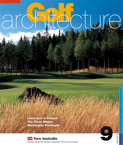 The Society of Australian Golf Course Architects produces an annual journal. Issue 9 (2006) included an essay written by me, entitled "Golf Design Tools: PAD vs. CAD." PAD stands for Pencil Aided Design and CAD computer aided design. This is a good primer for what I'll be describing tomorrow. Here is where you can purchase this issue and others SAGCA.
Monday, March 10, 2008
They didn't think it could be done.
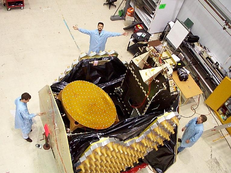 Unbeknownst to me, when I started on this program at Lockheed, the Program Manager thought the mechanical requirements were too great. He was partially correct, in that it couldn't have been done with the software and process that were in use at the time. Thankfully I was able to get approval to update both for the program - not that the other divisions like it at first.... Prior to this program there was no electonic concurrent engineering.
Pictured above is the completed "Doghouse" - the antenna payload without the reflectors. Please compare it to yesterdays electronic picture. The major difference is that the feeds are stowed. The installation of the two big feeds happens in two major steps. First we install them to the structure in the deployed position aligned to a few thousandths of an inch. Deployed because that is how they are used and the most critical position. A slight miss and in stead of covering China it is pointing in the Pacific. Next we stow them up and "hope" they fit to the mounting structure - the tolerance for fitting was tiny.
This is when the concurrent engineering comes into play. In the past when components were installed it was often found that some other program had changed design or location and there was now an interference. Something would have to be modified and possibly retested - never mind the documentation.
I was working closely with Frank (arms wide open above) when we first stowed the feeds. They were much more complicated, heavier and larger than any other feed structures. Usually the antenna is a 12 pound composite reflector. These were over 10 feet tall and 150 pounds. As the feed completely stowed - it happens very slowly - we looked at each other, and Frank had a look of amazement in his eyes. "I've never seen anything fit together like that in my 15 years here" was what he said. That is what CAD is most suited for.
What is CAD good for?
 CAD (Computer Aided Design) is great for aerospace, automotive, architecture - almost all manufacturing. In my opinion CAD is not ideal for golf design.
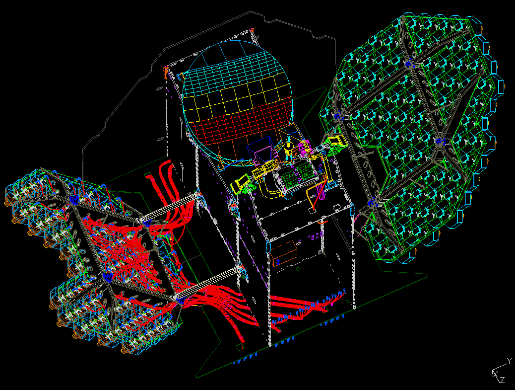
The above image is a CAD model of part of this satellite -- the part was called the "doghouse". Left is a transmit feed array - it transmits signals directly to the hand held mobile user on the earth ~23,000 miles away. Middle is a separate antenna that communicates with ground stations so a caller can speak with someone on the other side of the earth. To the right is the receive feed array that picks up the tiny signal from the mobile user.
How is CAD best utilized?
1. The above model was a moving dynamic assembly that had the mass, structural and thermal properties of all the components and the total assembly. Everything was modeled exactly as it was to be construted - it was a perfect (within thousandths of an inch any way) virtual replica of what we built.
2. Concurrent engineering. In projects involving large teams everyone can work with the same model and have ownership to their components. So if the propulsion, power or spacecraft structural groups made a change I'd see it live in my model just as they could see any part of the antenna in theirs.
3. Technical details and massive ability to repeat - those red string looking items are co-axial cables, and they are actually flexible in the computer model as in real life. There are little blue connectors at the ends and those are all instances of the same connector model - so if one changes they all changes.
Tommorrow I'm going to give an example of how CAD helped at Lockheed and the following day I will describe why I don't use CAD any longer.
Wednesday, March 5, 2008
Working in the field
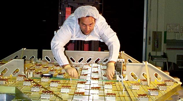 Sometimes I get asked why I work in the field. The above picture is a continuation of my previous work experience threads -- if you click aerospace either here or to the right under labels it will bring up the previous posts with that label.
A few items of note in the above image - I'm in Montreal integrating part of our structure (things with the holes) to a sub-contract item (yellow metal thing) which when combined got delived back to our plant for more integration and test. The item is a Receive Feed Array which is part of the antenna for the ACeS spacecraft. Incidently this piece that I am hanging over cost more than most golf courses - even in 1998 dollars. I'm wearing a hat, smock and gloves because the feed isn't supposed to get dirty. I went up with a team of three technicians - Steve, Frank and Chuck - for about a week. I mentioned Montreal because it is a very fine place to be for a week.
The traditional role of the engineer is to design and plan the system and write specs galore detailing the integration and test portions - this antenna needs to be placed in a rocket ship, survive launch into outer space then deploy and function. During the integration - or build - there are so many steps to check off and document that is usually a full time job in itself.
My first engineering job after college was with a large medical device company in one of their research and development departments. I used to hang out in the machine shops watching the parts and tools get built. Why? - because it made me a better designer - seeing how a ball end mill machines a radius stays in your mind as you design - it is so much more tangible.
So why am I lying on a gurney attached to a fork lift? One, no one else knew how to build this antenna without my instructions - at this point even I wasn't too sure how as it was a first of its kind. Two, it was a great learning experience for me and the crew. Three, it was a lot of fun - not just the Montreal part with Steve, Frank and Chuck.
What does this have to do with golf course deisgn? Everything. Some people may consider my efforts working on the construction at Wolf Point were for me to have some glossy images for my brochure and to say how I built the course. Some architects do practice this with great effect - especially pointing with rolled up drawings under thier ams. For me it was the same three above reasons -- I am the one with the most design details in my head and I don't think it is fruitful to draw every detail -- I learn how my instructions and intent get put in the dirt -- and it was fun. I didn't build Wolf Point - Don with his crew did - I did help a lot, sometimes crucially, and the reasons for my help are invaluable to me, Wolf Point and my future projects.
 I added this picture so it doesn't look like I did all the work. Cheers.
Monday, March 3, 2008
Golf Architecture Volume 4
 Paul Daley's next volume is on its way to the publisher. Yesterday's mention of my upcoming essay was referring to this edition. I was very pleased to have the pictorial essay entitled "Wolf Point Club Routing, USA — An Evolutionary Case Study" included. They are due to ship sometime this spring. The above is the cover image and here is Fullswing Golf Publishing's website - which should be updated soon - Paul has been quite busy putting it all together.
All of his books are excellent. I recommend picking up his past volumes, especially Volume 3 which included the following essay "Non-traditional paths to becomiong a golf course designer".
Sunday, March 2, 2008
Routing Plan and As-Built
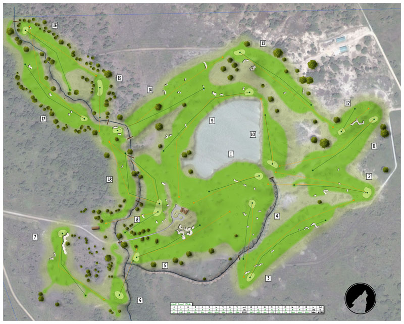 Here is Wolf Point Club in its entirity. The above image is the as-built routing plan. The design, GPS acquired data and the most current aerial photograph all laid out together. I've gotten some very nice feedback from those that I've show the plan and the person who has seen it most always thought it was exceptional. This spring an article about the evolution of the routing will be published. I look forward to sharing the process in detail here.
Subscribe to:
Posts (Atom)


